Chưa cập nhật
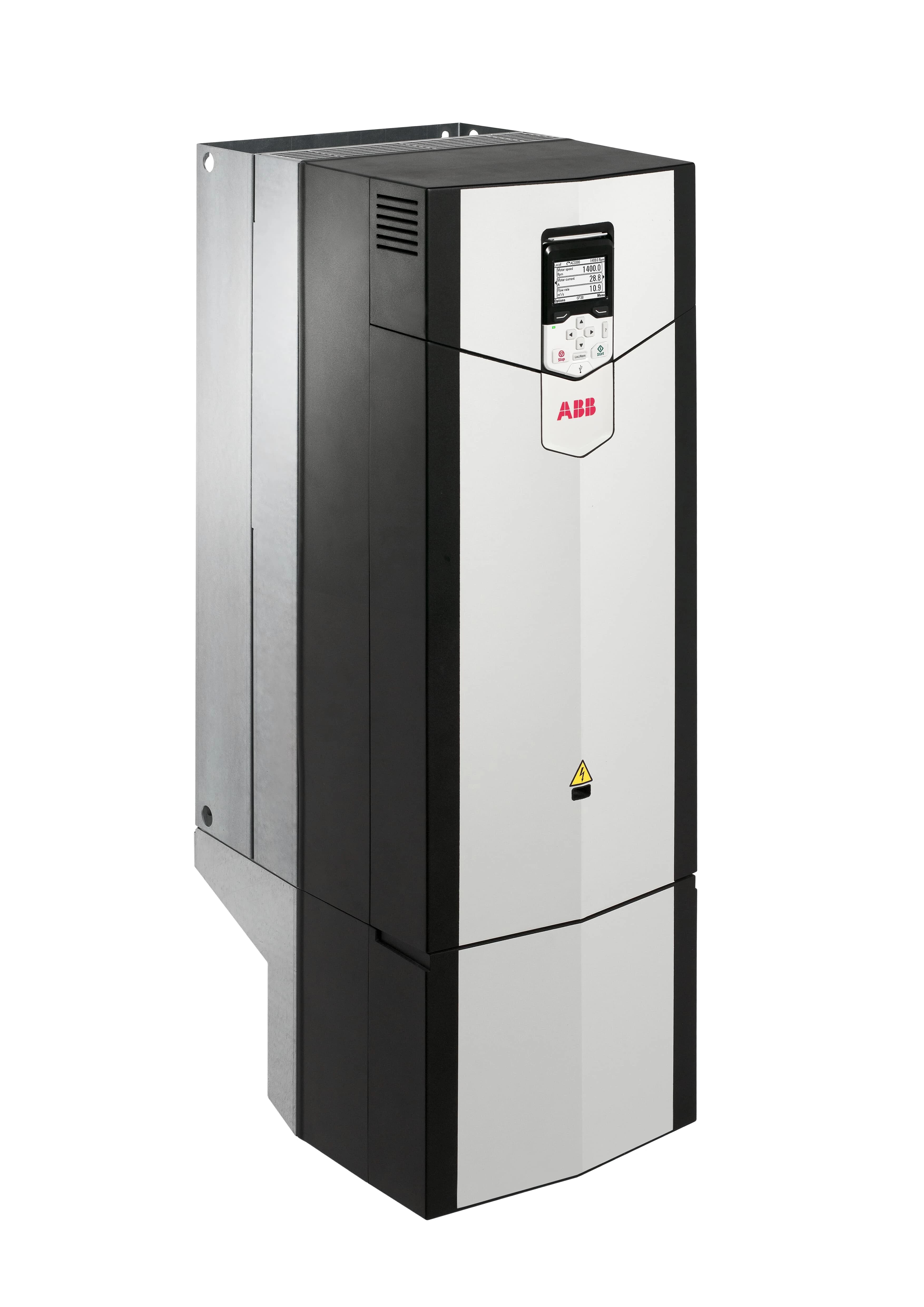
Mã hàng: ACS880-01-293A-3
- Đơn vị tính
- Chưa cập nhật
Đang tải nội dung…
Không cần thanh toán online. TESFA sẽ kiểm tra mã hàng, số lượng, điều kiện cung cấp và phản hồi báo giá theo thông tin liên hệ của bạn.
Với vật tư MRO, chọn đúng mã quan trọng hơn chọn theo ảnh. TESFA sẽ đối chiếu các điểm kỹ thuật chính trước khi xác nhận báo giá.

Khởi động từ ABB AF09-30-10-13. Product Net Width: 45 mm; Product Net Depth / Length: 77 mm.
Mã hàng
AF09-30-10-13
Đơn vị tính
Cái
Tình trạng cung ứng
Liên hệ báo giá
Số lượng cần mua (Cái)
Không cần thanh toán online. TESFA sẽ kiểm tra mã hàng, số lượng, điều kiện cung cấp và phản hồi báo giá theo thông tin liên hệ của bạn.
Với vật tư MRO, chọn đúng mã quan trọng hơn chọn theo ảnh. TESFA sẽ đối chiếu các điểm kỹ thuật chính trước khi xác nhận báo giá.
| Thuộc tính | Thông số sản phẩm |
|---|---|
| Mã sản phẩm | AF09-30-10-13 |
| Hãng sản xuất | ABB |
| Mã định danh ABB | 1SBL137001R1310 |
| Mã hàng theo CRM | AF09-30-10-13 / 1SBL137001R1310 |
| Model ABB | AF09-30-10-13 |
| Nhóm sản phẩm | Contactor |
| Model / type designation | AF09-30-10-13 |
| Product Net Width | 45 mm |
| Điện áp | 250 VDC |
| Product Net Depth / Length | 77 mm |
| Ghi chú xác minh | Thông tin được lấy từ dữ liệu CRM hiện có; TESFA sẽ đối chiếu lại mã hàng/cấu hình trước khi báo giá. |
| Product Net Height | 86 mm |
| Product Net Weight | 0.27 kg |
| Number of Main Contacts NO | 3 |
| Number of Main Contacts NC | 0 |
| Number of Auxiliary Contacts NO | 1 |
| Number of Auxiliary Contacts NC | 0 |
| Number of Poles | 3P |
| Standards | IEC/EN 60947-1, IEC/EN 60947-4-1, UL 60335-2-40 LZGH2 A2L, UL 60947-4-1, CSA C22.2 No. 60335-2-40 LZGH2 A2L, CSA C22.2 No. 60947-4-1 |
| Rated Operational Voltage | Auxiliary Circuit 690 V; Main Circuit 690 V |
| Rated Frequency (f) | Auxiliary Circuit 50 / 60 Hz; Control Circuit 50 / 60 Hz; Main Circuit 50 / 60 Hz |
| Conventional Free-air Thermal Current (I th ) | acc. to IEC 60947-4-1, Open Contactors Θ = 40 °C 35 A; acc. to IEC 60947-5-1, Θ = 40 °C 16 A |
| Rated Operational Current AC-1 (I e ) | (690 V) 40 °C 25 A; (690 V) 60 °C 25 A; (690 V) 70 °C 22 A |
| Rated Operational Current AC-3 (I e ) | (415 V) 60 °C 9 A; (440 V) 60 °C 9 A; (500 V) 60 °C 9.5 A; (690 V) 60 °C 7 A; (380 / 400 V) 60 °C 9 A; (220 / 230 / 240 V) 60 °C 9 A |
| Rated Operational Current AC-3e (I e ) | (415 V) 60 °C 9 A; (440 V) 60 °C 9 A; (500 V) 60 °C 9.5 A; (690 V) 60 °C 7 A; (380 / 400 V) 60 °C 9 A; (220 / 230 / 240 V) 60 °C 9 A |
| Rated Operational Current AC-15 (I e ) | (500 V) 2 A; (690 V) 2 A; (24 / 127 V) 6 A; (220 / 240 V) 4 A; (400 / 440 V) 3 A |
| Rated Operational Current DC-1 (I e ) | (110 V) 1-Pole, 40 °C 10 A; (110 V) 1-Pole, 60 °C 10 A; (110 V) 1-Pole, 70 °C 10 A; (110 V) 2 Poles in Series, 40 °C 25 A; (110 V) 2 Poles in Series, 60 °C 25 A; (110 V) 2 Poles in Series, 70 °C 22 A; (110 V) 3 Poles in Series, 40 °C 25 A; (110 V) 3 Poles in Series, 60 °C 25 A; (110 V) 3 Poles in Series, 70 °C 22 A; (220 V) 2 Poles in Series, 40 °C 10 A; (220 V) 2 Poles in Series, 60 °C 10 A; (220 V) 2 Poles in Series, 70 °C 10 A; (220 V) 3 Poles in Series, 40 °C 25 A; (220 V) 3 Poles in Series, 60 °C 25 A; (220 V) 3 Poles in Series, 70 °C 22 A; (72 V) 1-Pole, 40 °C 25 A; (72 V) 1-Pole, 60 °C 25 A; (72 V) 1-Pole, 70 °C 22 A; (72 V) 2 Poles in Series, 40 °C 25 A; (72 V) 2 Poles in Series, 60 °C 25 A; (72 V) 2 Poles in Series, 70 °C 22 A; (72 V) 3 Poles in Series, 40 °C 25 A; (72 V) 3 Poles in Series, 60 °C 25 A; (72 V) 3 Poles in Series, 70 °C 22 A |
| Rated Operational Current DC-3 (I e ) | (110 V) 1-Pole, 40 °C 6 A; (110 V) 1-Pole, 60 °C 6 A; (110 V) 1-Pole, 70 °C 6 A; (110 V) 2 Poles in Series, 40 °C 25 A; (110 V) 2 Poles in Series, 60 °C 25 A; (110 V) 2 Poles in Series, 70 °C 22 A; (110 V) 3 Poles in Series, 40 °C 25 A; (110 V) 3 Poles in Series, 60 °C 25 A; (110 V) 3 Poles in Series, 70 °C 22 A; (220 V) 2 Poles in Series, 40 °C 6 A; (220 V) 2 Poles in Series, 60 °C 6 A; (220 V) 2 Poles in Series, 70 °C 6 A; (220 V) 3 Poles in Series, 40 °C 25 A; (220 V) 3 Poles in Series, 60 °C 25 A; (220 V) 3 Poles in Series, 70 °C 22 A; (72 V) 1-Pole, 40 °C 25 A; (72 V) 1-Pole, 60 °C 25 A; (72 V) 1-Pole, 70 °C 22 A; (72 V) 2 Poles in Series, 40 °C 25 A; (72 V) 2 Poles in Series, 60 °C 25 A; (72 V) 2 Poles in Series, 70 °C 22 A; (72 V) 3 Poles in Series, 40 °C 25 A; (72 V) 3 Poles in Series, 60 °C 25 A; (72 V) 3 Poles in Series, 70 °C 22 A |
| Rated Operational Current DC-5 (I e ) | (110 V) 1-Pole, 40 °C 4 A; (110 V) 1-Pole, 60 °C 4 A; (110 V) 1-Pole, 70 °C 4 A; (110 V) 2 Poles in Series, 40 °C 10 A; (110 V) 2 Poles in Series, 60 °C 10 A; (110 V) 2 Poles in Series, 70 °C 10 A; (110 V) 3 Poles in Series, 40 °C 25 A; (110 V) 3 Poles in Series, 60 °C 25 A; (110 V) 3 Poles in Series, 70 °C 22 A; (220 V) 2 Poles in Series, 40 °C 4 A; (220 V) 2 Poles in Series, 60 °C 4 A; (220 V) 2 Poles in Series, 70 °C 4 A; (220 V) 3 Poles in Series, 40 °C 9 A; (220 V) 3 Poles in Series, 60 °C 9 A; (220 V) 3 Poles in Series, 70 °C 9 A; (72 V) 1-Pole, 40 °C 9 A; (72 V) 1-Pole, 60 °C 9 A; (72 V) 1-Pole, 70 °C 9 A; (72 V) 2 Poles in Series, 40 °C 25 A; (72 V) 2 Poles in Series, 60 °C 25 A; (72 V) 2 Poles in Series, 70 °C 22 A; (72 V) 3 Poles in Series, 40 °C 25 A; (72 V) 3 Poles in Series, 60 °C 25 A; (72 V) 3 Poles in Series, 70 °C 22 A |
| Rated Operational Current DC-13 (I e ) | (24 V) 6 A / 144 W; (48 V) 2.8 A / 134 W; (72 V) 1 A / 72 W; (110 V) 0.55 A / 60 W; (125 V) 0.55 A / 69 W; (220 V) 0.27 A / 60 W; (250 V) 0.27 A / 68 W; (400 V) 0.15 A / 60 W; (500 V) 0.13 A / 65 W; (600 V) 0.1 A / 60 W |
| Rated Operational Power AC-3 (P e ) | (400 V) 4 kW; (415 V) 4 kW; (440 V) 4 kW; (500 V) 5.5 kW; (690 V) 5.5 kW; (380 / 400 V) 4 kW; (220 / 230 / 240 V) 2.2 kW |
| Rated Operational Power AC-3e (P e ) | (415 V) 4 kW; (440 V) 4 kW; (500 V) 5.5 kW; (690 V) 5.5 kW; (380 / 400 V) 4 kW; (220 / 230 / 240 V) 2.2 kW |
| Rated Short-time Withstand Current Low Voltage (I cw ) | at 40 °C Ambient Temp, in Free Air, from a Cold State 10 s 150 A; at 40 °C Ambient Temp, in Free Air, from a Cold State 15 min 35 A; at 40 °C Ambient Temp, in Free Air, from a Cold State 1 min 60 A; at 40 °C Ambient Temp, in Free Air, from a Cold State 1 s 300 A; at 40 °C Ambient Temp, in Free Air, from a Cold State 30 s 80 A; for 0.1 s 140 A; for 1 s 100 A |
| Maximum Breaking Capacity | cos phi=0.45 (cos phi=0.35 for Ie > 100 A) at 440 V 250 A; cos phi=0.45 (cos phi=0.35 for Ie > 100 A) at 690 V 106 A |
| Rated Insulation Voltage (U i ) | acc. to IEC 60947-4-1 690 V; acc. to IEC 60947-5-1 690 V; acc. to UL/CSA 600 V |
| Rated Impulse Withstand Voltage (U imp ) | 6 kV |
| Maximum Electrical Switching Frequency | (AC-1) 600 cycles per hour; (AC-15) 1200 cycles per hour; (AC-2 / AC-4) 300 cycles per hour; (AC-3) 1200 cycles per hour; (DC-13) 900 cycles per hour |
| Maximum Mechanical Switching Frequency | 3600 cycles per hour |
| Rated Control Circuit Voltage (U c ) | 50 Hz 100 ... 250 V; 60 Hz 100 ... 250 V; DC Operation 100 ... 250 V |
| Power Loss | at 6 A per Pole 0.1 W; at Rated Operating Conditions AC-1 per Pole 0.8 W; at Rated Operating Conditions AC-3 per Pole 0.1 W |
| Operate Time | Between Coil De-energization and NC Contact Closing 13 ... 98 ms; Between Coil De-energization and NO Contact Opening 11 ... 95 ms; Between Coil Energization and NC Contact Opening 38 ... 90 ms; Between Coil Energization and NO Contact Closing 40 ... 95 ms |
| Mounting on DIN Rail | TH35-15 (35 x 15 mm Mounting Rail) acc. to IEC 60715; TH35-7.5 (35 x 7.5 mm Mounting Rail) acc. to IEC 60715 |
| Mounting by Screws (not supplied) | 2 x M4 Screws Placed Diagonally |
| Connecting Capacity Main Circuit | Flexible with Ferrule 1/2x 0.75 ... 6 mm²; Flexible with Insulated Ferrule 1x 0.75 ... 4 mm²; Flexible with Insulated Ferrule 2x 0.75 ... 2.5 mm²; Rigid Solid 1/2x 1 ... 4 mm²; Rigid Stranded 1/2x 1 ... 6 mm² |
| Connecting Capacity Auxiliary Circuit | Flexible with Ferrule 1/2x 0.75 ... 2.5 mm²; Flexible with Insulated Ferrule 2x 0.75 ... 1.5 mm²; Flexible with Insulated Ferrule 1x 0.75 ... 2.5 mm²; Rigid Solid 1/2x 1 ... 2.5 mm²; Rigid Stranded 1/2x 1 ... 2.5 mm² |
| Connecting Capacity Control Circuit | Flexible with Ferrule 1/2x 0.75 ... 2.5 mm²; Flexible with Insulated Ferrule 1x 0.75 ... 2.5 mm²; Flexible with Insulated Ferrule 2x 0.75 ... 1.5 mm²; Rigid Solid 1/2x 1 ... 2.5 mm²; Rigid Stranded 1/2x 1 ... 2.5 mm² |
| Wire Stripping Length | Auxiliary Circuit 10 mm; Control Circuit 10 mm; Main Circuit 10 mm |
| Degree of Protection | acc. to IEC 60529, IEC 60947-1, EN 60529 Auxiliary Terminals IP20; acc. to IEC 60529, IEC 60947-1, EN 60529 Coil Terminals IP20; acc. to IEC 60529, IEC 60947-1, EN 60529 Main Terminals IP20 |
| Tightening Torque | Auxiliary Circuit 1.2 N·m; Control Circuit 1.2 N·m; Main Circuit 1.5 N·m |
| Terminal Type | Screw Terminals |
| Product Name | Block Contactor |
| NEMA Size | 00 |
| Continuous Current Rating NEMA | 9 A |
| Horsepower Rating NEMA | (115 V AC) Single Phase 1/3 Hp; (200 V AC) Three Phase 1-1/2 Hp; (230 V AC) Single Phase 1 Hp; (230 V AC) Three Phase 1-1/2 Hp; (460 V AC) Three Phase 2 Hp; (575 V AC) Three Phase 2 Hp |
| Maximum Operating Voltage UL/CSA | Main Circuit 600 V |
| General Use Rating UL/CSA | (600 V AC) 25 A |
| Horsepower Rating UL/CSA | (120 V AC) Single Phase 3/4 hp; (200 ... 208 V AC) Three Phase 2 hp; (220 ... 240 V AC) Three Phase 2; (240 V AC) Single Phase 1-1/2 hp; (440 ... 480 V AC) Three Phase 5 hp; (550 ... 600 V AC) Three Phase 7-1/2 hp |
| Connecting Capacity Main Circuit UL/CSA | Rigid Solid 1/2x 16-10 AWG; Rigid Stranded 1/2x 16-10 AWG |
| Connecting Capacity Auxiliary Circuit UL/CSA | Rigid Solid 1/2x 18-14 AWG; Rigid Stranded 1/2x 18-14 AWG |
| Connecting Capacity Control Circuit UL/CSA | Rigid Solid 1/2x 18-14 AWG; Rigid Stranded 1/2x 18-14 AWG |
| Tightening Torque UL/CSA | Auxiliary Circuit 11 in·lb; Control Circuit 11 in·lb; Main Circuit 13 in·lb |
| Full Load Amps Motor Use | (120 V AC) Single Phase 13.8 A; (200 ... 208 V AC) Three Phase 7.8 A; (220 ... 240 V AC) Three Phase 6.8 A; (240 V AC) Single Phase 10 A; (440 ... 480 V AC) Three Phase 7.6 A; (550 ... 600 V AC) Three Phase 9 A |
| Ambient Air Temperature | Close to Contactor Fitted with Thermal O/L Relay -25 ... 60 °C; Close to Contactor without Thermal O/L Relay -40 ... 70 °C; Close to Contactor for Storage -60 ... +80 °C |
| Climatic Withstand | Category B according to IEC 60947-1 Annex Q |
| Maximum Operating Altitude Permissible | Without Derating 3000 m |
| Resistance to Shock acc. to IEC 60068-2-27 | Closed, Shock Direction: B1 25 g; Open, Shock Direction: B1 5 g; Shock Direction: A 30 g; Shock Direction: B2 15 g; Shock Direction: C1 25 g; Shock Direction: C2 25 g |
| Resistance to Vibrations | 4g Closed Position & 2g Open position 5 ... 300 Hz |
| Pollution Degree | 3 |
Mã hàng: ACS880-01-293A-3
Mã hàng: ACS880-01-032A-3
Mã hàng: ACS880-01-072A-3
Mã hàng: ACS880-01-045A-3
Hướng dẫn đọc mã van điện từ SMC dòng SY3000, SY5000, SY7000 và SY9000 theo catalog hãng, kèm ví dụ SKU thật và checklist tránh đặt nhầm cấu hình.
Theo đường đi của khí nén để hiểu tiền điện đến từ đâu, tính thử chi phí và chuẩn bị checklist kiểm tra rò rỉ trong nhà máy.
Chọn ống khí PU/PA theo kích thước, áp suất tại nhiệt độ dùng, bán kính uốn và môi trường. Có bảng đối chiếu và checklist thay ống MRO.